
Before describing the work on this pedalboard, it is worth noting that my original pedalboard was known as Allen Organ’s “Princess” pedalboard – something I learned only recently from a YouTube video. The “Princess” pedalboard is a slightly compacted pedalboard, which (in my opinion) is unfortunate. It is approximately 4-5 inches narrower than a ‘standard’ AGO (American Guild of Organists) pedalboard (concave and radiating), or other ‘standard’ pedalboards such as those of the German BDO (Bund Deutscher Orgelbaumeister, or Federation of German Master Organ Builders) which includes options for straight flat, straight concave, and radiating concave pedalboards.
I put ‘standard’ in quotes because there are so many ‘standards’ that it is hard to reference only one as being the ‘gold standard.’ Having said that, however, I have always found the Allen Princess pedalboard to be ‘sub-standard’ and very difficult to play – much more so than any other ‘standard’ pedalboard whether straight, concave, or concave and radiating.
After much consideration, I built the new pedalboard described below to reflect the BDO standard for a straight concave pedalboard, partly because it was easier to build than a concave radiating pedalboard, but mostly because I have never been convinced that there is any advantage to the radiating pedalboard (at least for the music I usually play). I have found it easy to switch between my straight, concave BDO pedalboard and a standard AGO pedalboard (which is common for most US built organs including the one at my church) because they are very similar in width.
The first step in building the new pedalboard was to obtain the critical dimensions from various websites (mostly relying on the Laukhuff Catalog, page 9.16 diagram) and create some full-size plywood templates for construction. The photos below show portions of a side view. I show them just as examples as both templates are unique to the case design I had in mind and the springs I salvaged from the old Allen pedalboard. Another end view template showed the curves for the pedalboard, but because it was later cut up to make cutting guides, I have no photos of that template. Making the full-size templates allowed me to work out construction details before actually starting construction and guaranteed that the critical dimensions would not get lost along the way.

Template
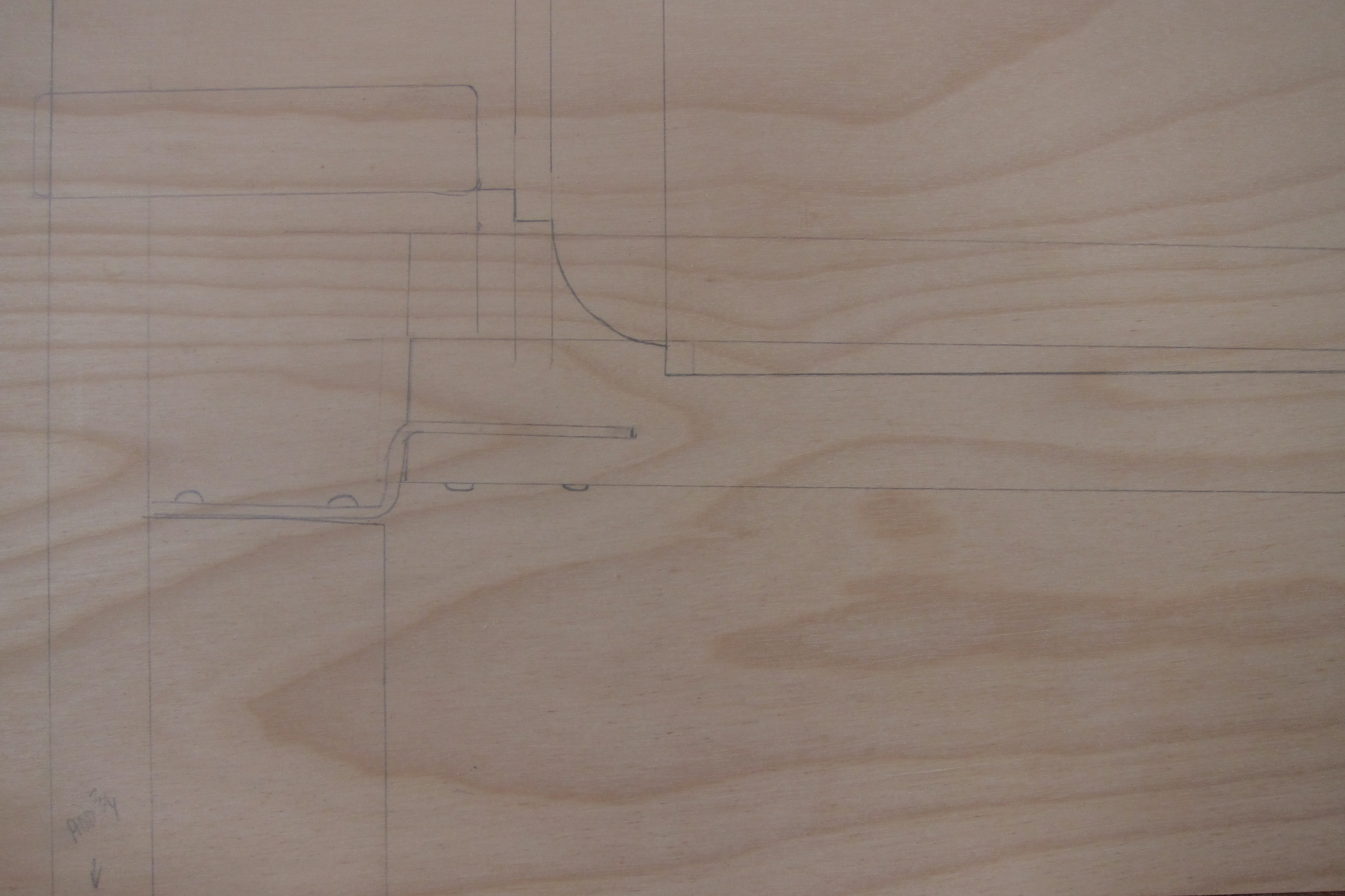
Template
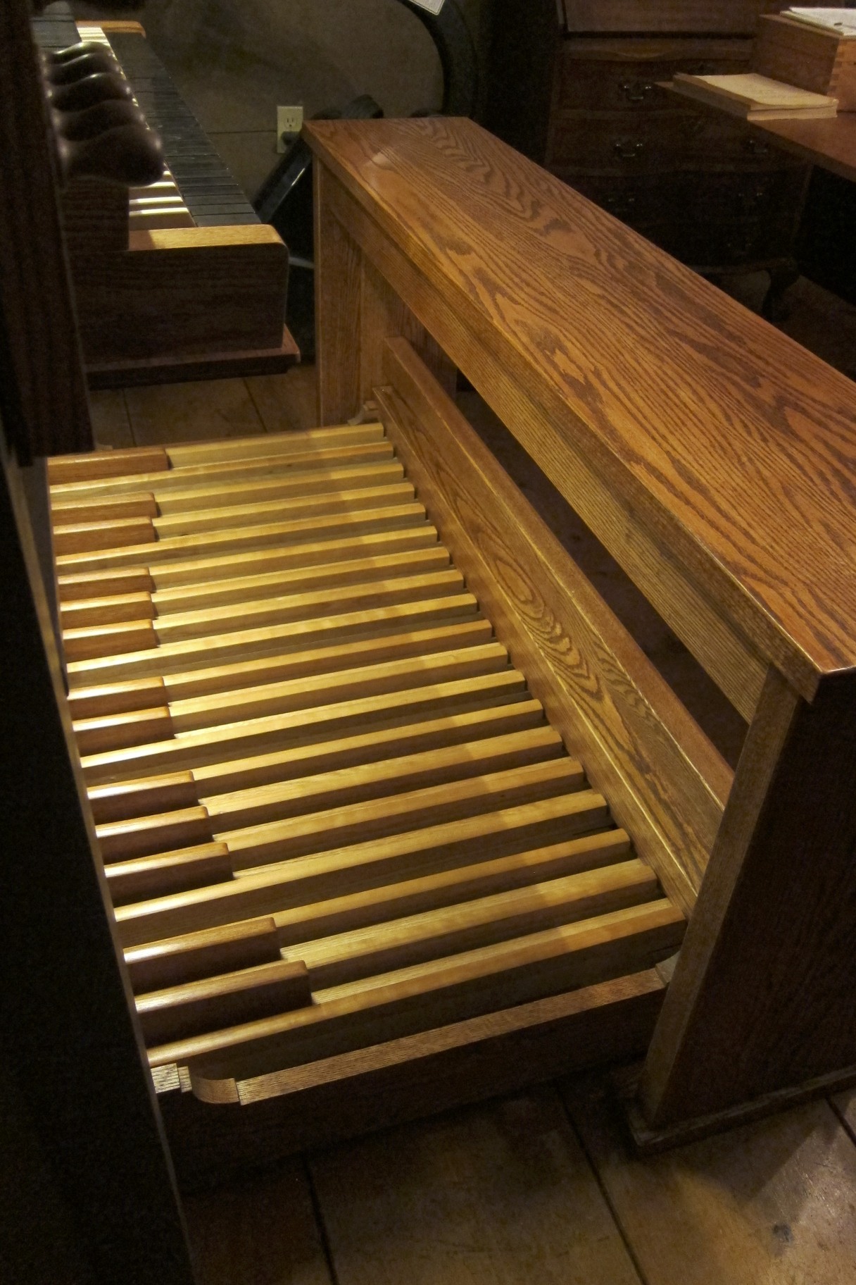
The pedalboard case was constructed of red oak as were the lower parts of the pedals which were ‘capped’ with American cherry for the naturals, and Brazilian cherry for the sharps. The caps should darken considerably over time, but the Brazilian cherry should darken more than the American cherry. I wanted the darker than usual caps because my keyboards are ‘reversed’ color and I thought that a darker pedalboard would best compliment the keyboards. All wood parts were finished with multiple coats of Waterlox finish (a highly modified tung oil, often used on gym floors.)* The ‘springs’ at the rear are spring steel salvaged from the original Allen pedalboard.
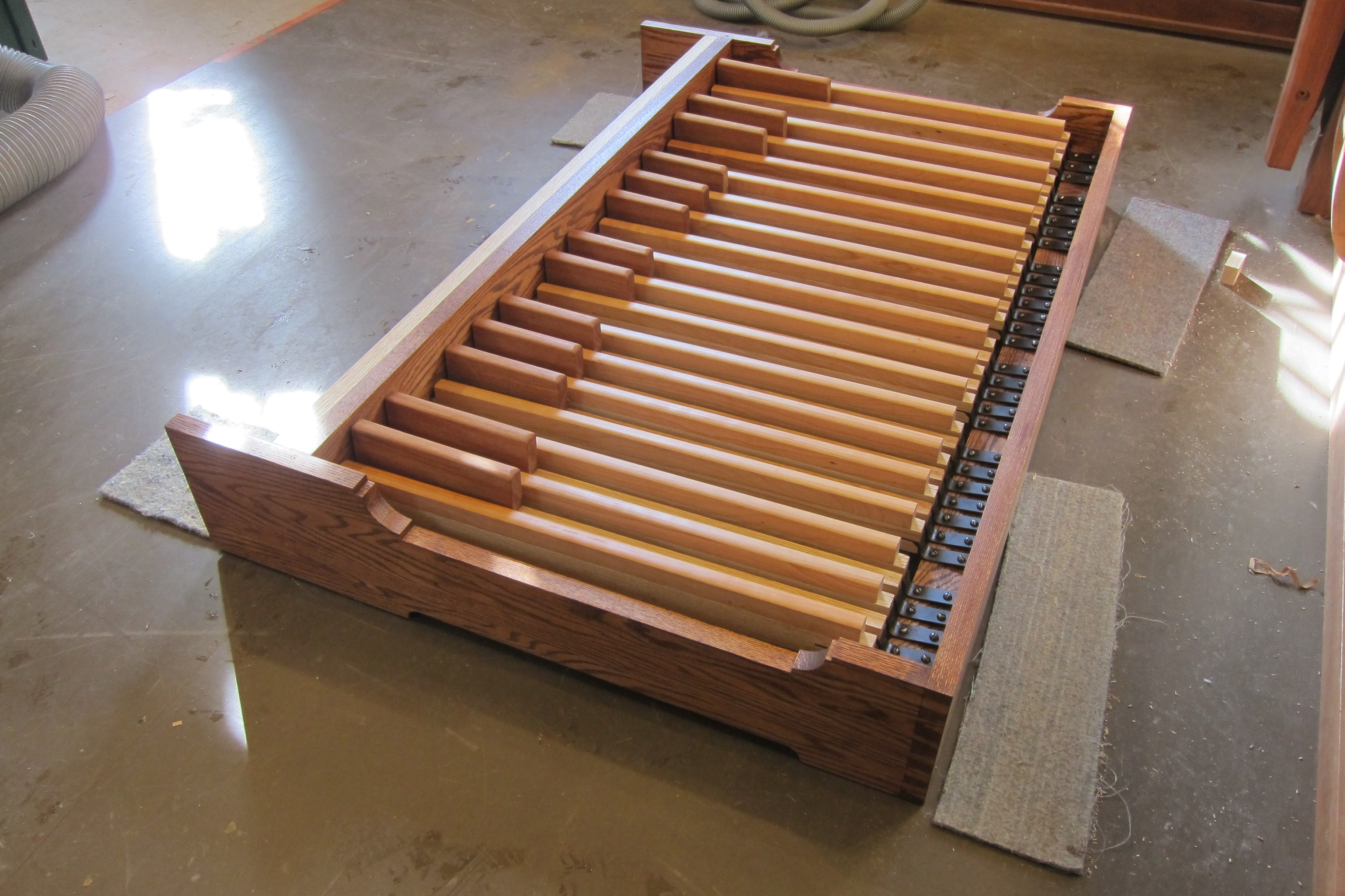
Pedalboard

Pedalboard Springs
The mechanism for holding the front of the pedals varies greatly from pedalboard to pedalboard, but in every case the essentials seemed to involve restraining the pedal tightly enough and with enough padding to give it a solid, yet quiet movement up and down. Initially I decided that the most straightforward way to accomplish this would be to use some very slippery ultra high molecular weight plastic to separate the pedals. The idea of using slippery plastic in a pedalboard is not original to me. I had hoped that the low friction afforded by the plastic alone would result in a sufficiently quiet pedalboard, and it was at least as quiet as some tracker action pedalboards that I have heard, but it was a bit too noisy for a smaller room. After using it for several days, I decreased the width of the plastic guides just enough to add some self-adhesive felt (From Howard Piano Industries) to the sides of the pedals where they contacted the plastic. After doing this, the pedal movement became almost whisper quiet. The top and bottom of the pedal travel are cushioned with some woven carpet underlayment that I’ve had for years. These strips are about 3/8″ thick (compressing to about 1/4″ thick) and about 1″ wide. I think the material is entirely synthetic. Thick felt could easily have been used instead. The photo below shows the ends of the pedals as they pass through the front of the pedalboard (the felt was added after this photo).

Pedal guides (before felt was added)
Each pedal was outfitted with a 1/4″ cylindrical magnet (Apex Magnets) fitted into a 1/4″ hole in a 1/4″ piece of plywood and secured by a drop of shellac finish. The slot in the plywood allows for adjustment up and down to fine tune the firing point for each pedal.
I chose to use reed switches from Testco.com (part number CT10-1040-G1) because their reed switches are encased in rectangular plastic cases which makes them much more robust than those that are glass encased. Although they are designed to be mounted on circuit boards, they are relatively easy to mount in various other ways.
Each switch was prepared by soldering a wire on each end and connecting the wires to Midi Gadgets Boutique bo10 breakout adaptors which were in turn connected by 10 conductor ribbon wires to a sm8x8 scan matrix board also from Midi Gadgets. For convenience in connecting to the main organ case, the output from this board was passed through a standard D-25 connector and eventually to a hwce-max MIDI board also from Midi Gadgets.
The reed switches were positioned in 1/8″ slots cut into a board curved to match the pedalboard curve and secured with a thin pine strip screwed down from the top using brass screws to eliminate any magnetic field from steel screws, some of which would be very near a reed switch.
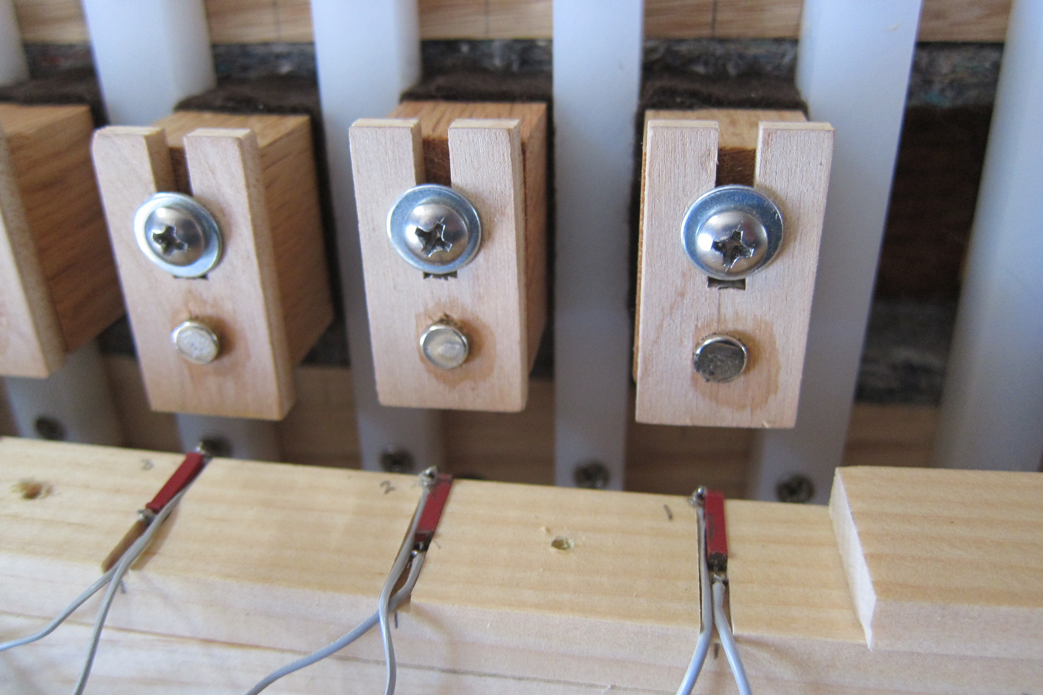
Pedalboard Magnets and Reed Switches
The photo below shows the entire pedalboard wiring (every 8 pedals to a breakout adaptor) and from each breakout by ribbon cable to the sm8x8 scan matrix, and finally to the D-25 connector for the connecting cable from the organ case.
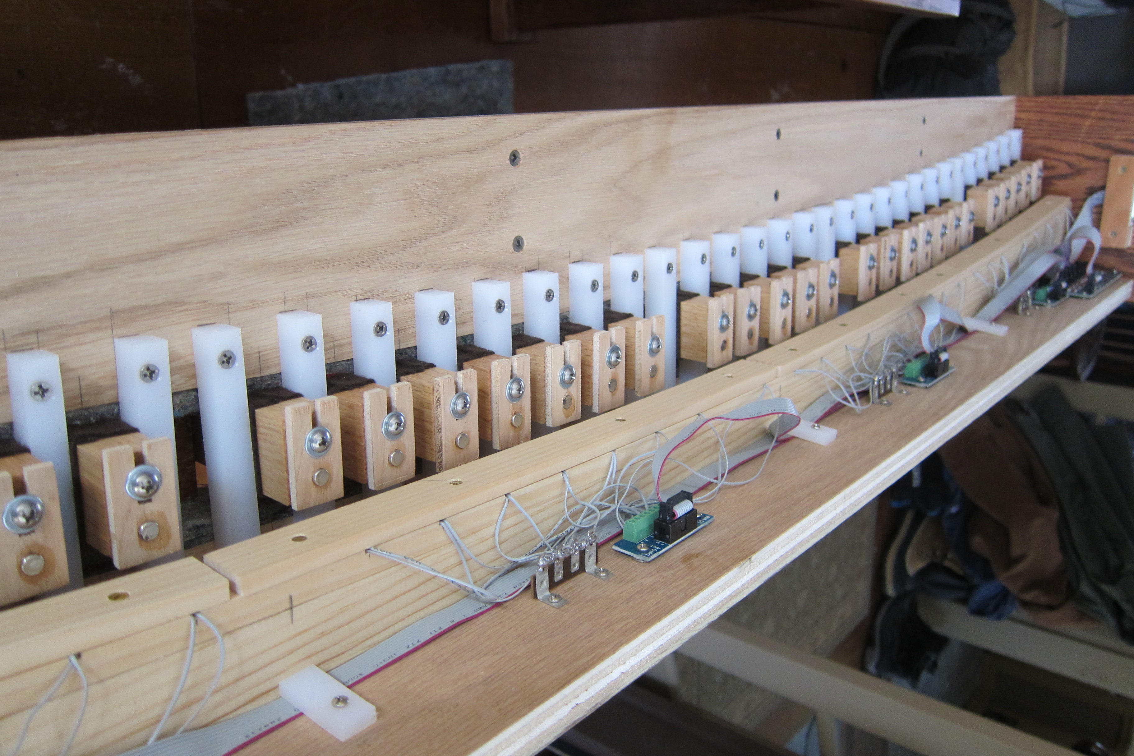
Pedalboard wiring with D-25 Connector on far end.

Scan matrix board (mostly hidden) and D-25 connector.
After an initial fine tuning of the steel springs for about 3 lbs of touch near the front of the sharp keys, and a final tuning of the firing point for each pedal, the pedalboard has functioned without any problems. I have found it much easier to play than the older more compact pedalboard. A new bench was part of this project from the start as the old Allen bench was not wide enough to accommodate the new pedalboard.
Finished Pedalboard and Bench
