
Several years ago I made some Baroque-style organs stops as described here. I liked these stops, but eventually abandoned them in favor of Launchpads which were much more flexible. I liked the Launchpads and found them very functional except that they seemed quite small (including any stop label overlays where the text had to be very small.) Last year I began giving some additional thought to the Baroque-style stops and decided to build another prototype that included LED lights to indicate the status of each stop.
They say that one picture is worth a thousand words, but as I’ve looked over my photos of the new stop control construction, I fear that each one needs a thousand words to describe it. Not every detail is as clear as I had hoped. I’ll post enough photos with comments below to give some sense of how they were made, but please feel free to contact me for additional information.
The basic framework is show below for one unit that contains 8 stop controls that will be mounted vertically in the stop jambs. (See photo at the bottom of this page.)
All of the plywood pieces are cabinet-grade birch (not construction plywood.) The base is 1/2″ thick and the blocks between which the stop controls will slide are 3/4″ spaced 3/4″ apart (using temporary spacers to insure precision placement). The extra grooves are described below and are sized for some fiber optic cable which will transmit light from LEDs on the back of the unit to the front. The blocks are glued and nailed to the base with a couple small nails. The whole unit was finished with a couple coats of shellac to seal the surfaces. The channels for the stop controls are spaced at 2 1/2″ on center for my stops. I think the dimensions could be changed considerably to accommodate larger stop pulls or a different size stop jamb.
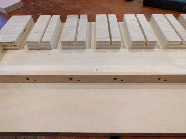
Each stop channel is lined with self-adhesive felt, and the square pieces between the channels are good quality self-adhesive furniture felt used to deaden sound as the stop controls are pulled out.

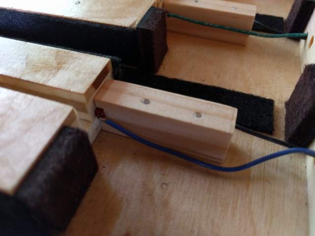
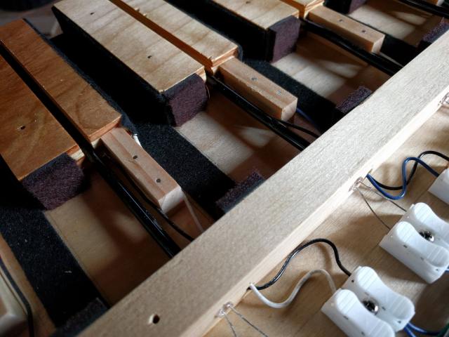
A reed switch is mounted perpendicular to each channel and held in place by the small pine holders and a couple of nails. These are the same switches described elsewhere on this site. Wires from each are connected to some push-style connectors at the rear of the unit. The strip in the middle contains the LED lights for which only the wires are easily visible. They connect directly to the push-type connectors. The LEDs sit in holes that are drilled all the way through the strip. The holes will also hold lengths of fiber optic cable that will carry the light to the front of the unit (not yet installed in the photo.)
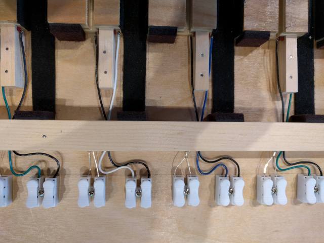
The barely visible reed switches are in red. The felt at the right in this photo (rear of the unit) deadens the sound of the stop control as it is pushed in.
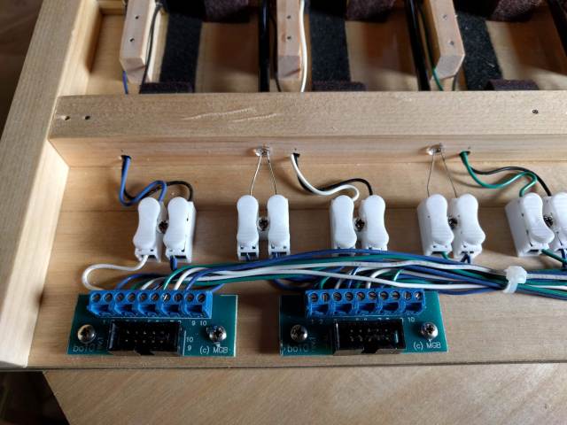
All of the wiring is connected to some Midi-boutique IDC connectors (and then on to the control boards, also from Midi-boutique. One connector is for the reed switches, the other for the LEDs. ) The switches connect via IDC cable to my midi boards.
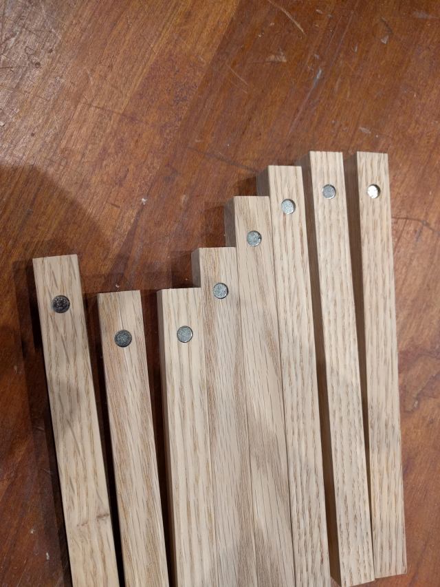
The actual stop controls are shown below with 1/4″ cylindrical magnets press fitted into the controls. They were made from ash selected to be more-or-less quarter-sawn to guarantee the most stability. The stop controls are approx. 5/8″ square, but were sized to slide easily (but still have some resistance) through the felt lined channels.
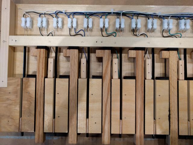
The photo below shows the stop controls in their channels. Note that a small piece has been glued to the end of each to limit the travel toward the front piece of felt. The magnets are to the right and move toward the reed switches as the stops are pulled out. Note also that short pieces of black covered 3/16″ fiber optic cable have been installed to transmit the LED light to the front of the unit. The cables are held in position near the front with small pieces of plywood and a small dab of glue. The LEDs could probably have been mounted directly at the front, but the fiber optic cable provides a nice round light about 1/8″ in diameter at the front and eliminates the need for a lot of wires through to the front.
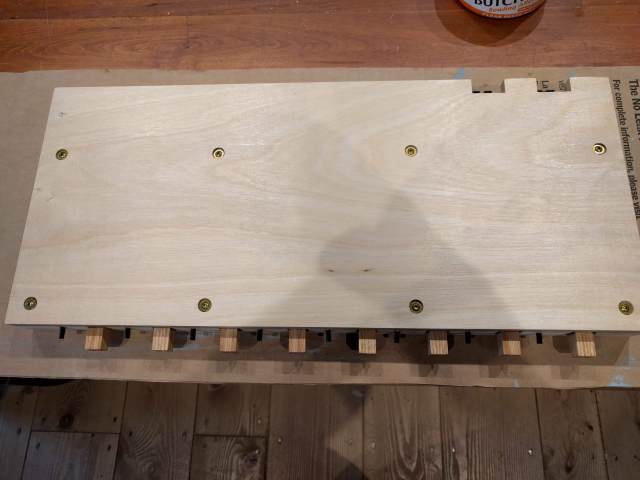
The entire unit receives another 1/2″ piece of plywood to complete the unit. This piece has felt strips over each stop channel. Each unit has 8 stops (which matches the connectors and matrix control boards I have.) Each unit is mounted vertically in the stop jambs and covered by a 1/8″ painted masonite front-piece as shown below. Because there is not much room for error on these relatively small stop pull units, I tried to keep each overall unit within about 1/16″ tolerance relative to the others and the stop spacings, fiber optic holes, etc. to about 1/32.” Minimal adjustment was needed when mounting them so that the front cover would fit reasonably well (though it did not fit perfectly!)
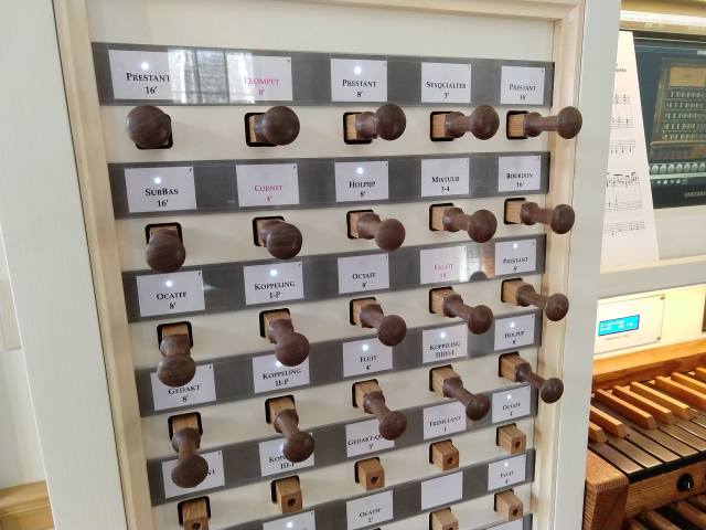
Each stop control has a turned knob that is friction-fit into a hole at the end. I have yet to complete turning all the knobs. The stop labels slide into slots on either side and are made of 1/8″ acrylic strips. The printed stop labels are attached to the back side of the acrylic with a spray adhesive that amazingly is essentially invisible from the front.
These stop controls have been incorporated into a new Baroque-style console shown below.

